drawing 3d objects in opengl clear
[index]
Vertex Buffer Objects
Anton Gerdelan. Last Updated two October 2016
A vertex buffer object (VBO) is nothing fancy - it's just an array of data (usually floats). Nosotros already had a expect at the almost basic apply of vertex buffer objects in the Hello Triangle tutorial. We know that nosotros can describe a mesh in an array of floats; {x,y,z,x,y,z..x,y,z}. And we also know that we need to utilize a Vertex Array Object to tell OpenGL that the assortment is divided into variables of three floats each.
The key idea of VBOs is this: in the former, "immediate-mode" days of OpenGL, before VBOs, nosotros would ascertain the vertex information in main memory (RAM), and re-create them one-by-one each time that we describe. With VBOs, we re-create the whole lot into a buffer before cartoon starts, and this sits on the graphics hardware retention instead. This is much more efficient for drawing because, although the bus between the CPU and the GPU is very wide, a clogging for drawing performance is created when drawing operations stall to send OpenGL commands from the CPU to the GPU. To avert this we endeavour to keep as much information and processing on the graphics hardware as we can.
A VBO is not an "object" in the object-oriented programming sense, it is a simple array of data. OpenGL has several other types of data that it refers to equally singular "buffer objects". I assemble that the term "object" here implies that OpenGL gives us a handle or identifier number to the whole buffer to interact with, rather than a traditional address to the first element in the buffer. I should probably refer to these as "buffer objects" everywhere, but I'chiliad not 1 for pedantry, and then I use "vertex buffer", and "vertex buffer object" interchangeably in the text.
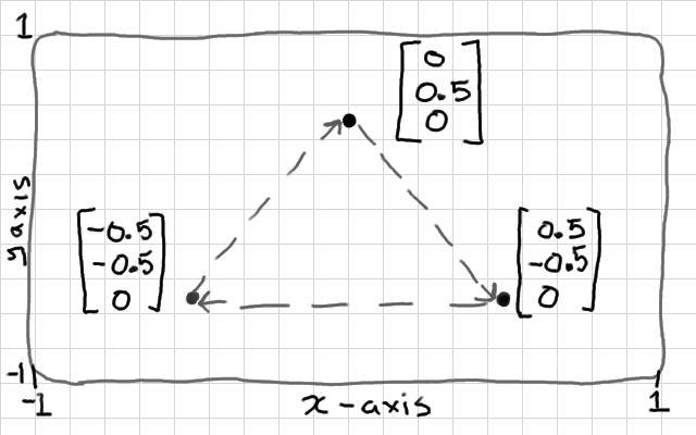
This shape might accept a vertex buffer: {0, 0.five, 0, 0.5, -0.5, 0, -0.5, -0.5, 0}
We will await at managing vertex buffers in a little chip more depth. We will need this for enabling lighting and texturing effects afterwards. We volition break downwards the interface, and visualise how interpolation betwixt the vertex shader and the fragment shader works.
Rendering Different Archaic Types
Write up a working demo that renders a triangle. You might utilize Hello Triangle if yous haven't got one already. Then we tin play with the glDrawArrays() function. So far, nosotros have just looked at rendering triangles from sets of 3 points, simply you tin actually return in several dissimilar modes:
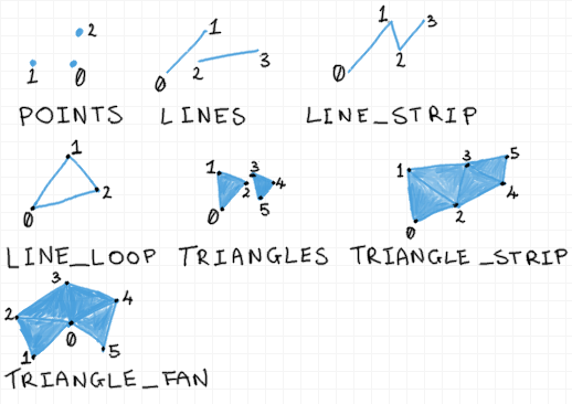
Effort changing your GL_TRIANGLES parameter. You tin can meet that points and lines are going to exist useful for drawing affair like charts or outlines. Triangle strip is a slightly more than efficient method for drawing ribbon-like shapes. I've never institute a legitimate apply for triangle fans. You tin can really alter the size of the points in the vertex shader, and so they are quite versatile. Lines no longer have very practiced supporting functions, so they're non as useful.
But How Do I Return a Wire-Frame Way?
All of my students tried to make a wire-frame rendering mode so I thought I'd point this out here - it's much easier to employ the born function than to endeavor to draw everything with GL_LINES. Call glPolygonMode(GL_FRONT, GL_LINE); earlier rendering.
Using Multiple Vertex Buffers for One Object
We tin store more than merely 3d points in a vertex buffer. Common uses also include; second texture coordinates that describe how to fit an image to a surface, and 3d normals that describe which style a surface is facing and then that we can calculate lighting. And so it's quite likely that most of your objects will have 2 or 3 vertex buffers each.
You can use vertex buffers to hold any data that you similar; the cardinal thing is that the data is retrieved in one case per vertex. If you tell OpenGL to draw an assortment of 3 points, using a given vertex assortment object, then it is going to launch 3 vertex shaders in parallel, and each vertex shader will get a i variable from each of the attached arrays; the first vertex shader will become the first 3d betoken, 2d texture coordinate, and 3d normal, the second vertex shader will get the second 3d point, 2nd texture coordinate, and 3d normal, then on, where the number of variables, and size of each variable is laid out in the vertex array object.
Define Vertex Colours
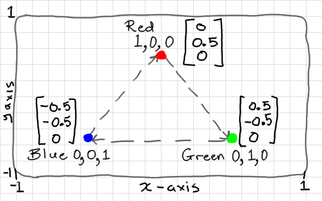
Vertex colours are very seldom used in practise, but most modern GL tutorials will get you to create a buffer of colours every bit a 2nd vertex buffer. Why? Because it's easy to visualise how interpolation works with colours. So permit'south exercise that - our colours will exist similar to 3d points - except they volition accept r,g,b values of 0.0 to one.0 instead of positions. Let'southward use our triangle of points again (as pictured in a higher place), and brand a buffer of colours with ane vertex completely blue, one completely cerise, and ane completely green.
float points[] = { 0.0f, 0.5f, 0.0f, 0.5f, -0.5f, 0.0f, -0.5f, -0.5f, 0.0f }; float colours[] = { 1.0f, 0.0f, 0.0f, 0.0f, 1.0f, 0.0f, 0.0f, 0.0f, i.0f }; Yous tin can run across that the color values are going to stand for to the position values. Example:
Create VBOs
Okay, at present for each ane we tin create a GL vertex buffer object, bind information technology in the land machine, and re-create the array of values into it. Both colours, and points have ix components each (three vertices with 3 components per vertex). We fix ane buffer subsequently the other, because the state auto tin can but have 1 buffer bound at a time.
GLuint points_vbo = 0; glGenBuffers(1, &points_vbo); glBindBuffer(GL_ARRAY_BUFFER, points_vbo); glBufferData(GL_ARRAY_BUFFER, 9 * sizeof(float), points, GL_STATIC_DRAW);
GLuint colours_vbo = 0; glGenBuffers(ane, &colours_vbo); glBindBuffer(GL_ARRAY_BUFFER, colours_vbo); glBufferData(GL_ARRAY_BUFFER, 9 * sizeof(float), colours, GL_STATIC_DRAW);
Define VAO
Our object now consists of two vertex buffers, which volition exist input "attribute" variables to our vertex shader. Nosotros ready the layout of both of these with a single vertex array object - the VAO represents our complete object, and so we no longer demand to continue rail of the individual VBOs.
Notation that we have to demark each VBO before calling glVertexAttribPointer(), which describes the layout of each buffer to the VAO.
The first parameter of glVertexAttribPointer() asks for an alphabetize. This is going to map to the indices in our vertex shader, so we demand to give each attribute hither a unique index. I volition requite my points alphabetize 0, and the colours alphabetize 1. We will make these lucifer up to the variables in our vertex shader afterward. If y'all accidentally get out both indices at 0 (piece of cake enough to exercise when re-create-pasting code), then your colours will be read from the position values so x→red y→green and z→blue.
Both buffers contain arrays of floating point values, hence GL_FLOAT, and each variable has 3 components each, hence the 3 in the second parameter. If you accidentally get this parameter incorrect (quite a common mistake), then the vertex shaders will be be given variables fabricated from the wrong components (e.yard. position ten,y,z gets values read from a y,z,x).
GLuint vao = 0; glGenVertexArrays(one, &vao); glBindVertexArray(vao); glBindBuffer(GL_ARRAY_BUFFER, points_vbo); glVertexAttribPointer(0, 3, GL_FLOAT, GL_FALSE, 0, NULL); glBindBuffer(GL_ARRAY_BUFFER, colours_vbo); glVertexAttribPointer(1, 3, GL_FLOAT, GL_FALSE, 0, NULL);
That is the mesh side taken intendance of - you only need to practice this part one time, when creating the object. There is no demand to repeat this lawmaking inside the rendering loop. Just keep track of the VAO index for each blazon of mesh that you create.
Enable Vertex Arrays 0 and i in a VAO
Okay, then we created a vertex assortment object, and described ii attribute "pointers" within it. Unfortunately, attributes are disabled by default in OpenGL 4. Nosotros demand to explicitly enable them too. This is piece of cake to get incorrect or overlook, and is not well explained in the documentation. We use a function called glEnableVertexAttribArray() to enable each i. This function only affects the currently jump vertex array object. This means that when we do this now, it volition only affect our attributes, above. We will need to bind every new vertex array and repeat this procedure for those too.
glEnableVertexAttribArray(0); glEnableVertexAttribArray(1);
Nosotros are using ii attributes (points and colours), and we know that these are numbered 0 (points), and 1 (colours); matching the numbers nosotros gave when setting upwards the vertex attribute pointers, before.
A trivial aside well-nigh this...
Other GL incarnations don't have vertex array objects, and need to explicitly enable and disable the attributes every time a new type of object is drawn, which changes the enabled attributes globally in the country machine. Nosotros don't demand to worry about that in OpenGL iv; the vertex attribute object will recall its enabled attributes. i.e. they are no longer global states. This isn't clear in the official documentation, nor is it explained properly in other tutorials - information technology's very easy to get a faux-positive misunderstanding of how these things piece of work and see hair-pulling bug afterwards when you're trying to draw 2 dissimilar shapes. I really figured this out by writing a programme that used the scientific method to endeavour and falsify (break in every believable way) my theory for how the logic of attribute enabling worked; if I'd just tried it until it worked (deduction) so I'd have been wrong! Well...I just don't know what to say...the bind/enable design is not a expert one.
If yous forget to enable an attribute, the shader won't know where to read the data from and you lot'll become weird results e.thou. black colours. I believe attribute 0 is enabled past default, but the second attribute that we added will not be. This procedure is a bit excessive, and I feel should really be handled internally by OpenGL, only in this version nosotros still need to do information technology.
Modify the Vertex Shader
Now, we want our shader to return using the 2nd vertex buffer, so nosotros need to add a second aspect to the top of the vertex shader. Nosotros are going to add the OpenGL 4 layout prefix to each aspect. This lets us manually specify a location for each attribute - and we are going to match this up to the index that nosotros gave each ane in glVertexAttribPointer. If you don't specify a location, the shader programme linker will automatically assign one. Yous can query this, which we did in Shaders, only I prefer to specify it manually so I can encounter the values as I write.
layout(location = 0) in vec3 vertex_position; layout(location = 1) in vec3 vertex_colour; out vec3 colour; void chief() { color = vertex_colour; gl_Position = vec4(vertex_position, 1.0); } Now, the other interesting alter here is that I took the vertex_colour input attribute and gave it to an output variable, which I called color. This is where information technology gets interesting. It has no effect on our vertex shader, but outputs it to the next stage in the programmable hardware pipeline. In our example - the fragment shader.
If y'all desire your GLSL code to exist compatible with OpenGL 3.2, for example, and so that information technology runs on a Mac, then yous can't use the layout keyword. Y'all can achieve the exact same effect by telling the shader's linker which variable should have which location. Right afterwards compiling but before linking, you can call glBindAttribLocation() to do this:
... glCompileShader(my_vertex_shader); glCompileShader(my_fragment_shader); glAttachShader(shader_programme, my_fragment_shader); glAttachShader(shader_programme, my_vertex_shader); // insert location binding code here glBindAttribLocation(shader_programme, 0, "vertex_position"); glBindAttribLocation(shader_programme, ane, "vertex_colour"); glLinkProgram(shader_programme); ...
You lot don't demand to utilise both methods - one or the other is fine. The tertiary choice is to let the linker decide which location to requite each input variable, and so you use a value returned by glGetAttribLocation() for the first parameter of calls to glVertexAttribPointer().
Alter the Fragment Shader
Nosotros can rewrite the fragment shader to use our new color variable equally an input, which volition color each fragment directly. Note that we add together an in prefix to retrieve a variable from a previous stage. This in/out convention is a little different to how other OpenGL versions work. Our output fragment color needs to exist r,k,b,a (4 components) so we can merely add a 1 to the stop of our 3-component color by casting information technology every bit a vec4.
in vec3 colour; out vec4 frag_colour; void chief() { frag_colour = vec4(color, one.0); } Test It
That'south it! Our drawing loop should look the aforementioned equally with the Howdy Triangle demo. Note that it's just the single VAO that needs to be bound for drawing; other GL implementations will have yous bind both arrays, just not OpenGL 4:
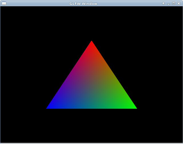
while(!glfwWindowShouldClose(window)) { glClear(GL_COLOR_BUFFER_BIT | GL_DEPTH_BUFFER_BIT); glUseProgram(shader_programme); glBindVertexArray(vao); glDrawArrays(GL_TRIANGLES, 0, three); glfwPollEvents(); glfwSwapBuffers(window); if(glfwGetKey(window, GLFW_KEY_ESCAPE)) { glfwSetWindowShouldClose(window, ane); } } You lot tin test that it works now!
Vertex Shader to Fragment Shader Interpolation
Now, remember, our triangle has merely 3 vertices, but 1 fragment for every pixel-sized area of the surface. This means that we have three colour outputs from vertex shaders, and possibly 100 colour inputs to each fragment shader. How does this work?
The answer is that each fragment shader gets an interpolated colour based on its position on the surface. The fragment exactly on the scarlet corner of the triangle volition be completely red (1.0, 0.0, 0.0). A fragment exactly half-way betwixt the blueish and red vertices, along the border of the triangle, will be majestic; half cerise, one-half blueish, and no greenish: (0.5, 0.0, 0.5). A fragment exactly in the middle of the triangle volition be an equal mixture of all 3 colours; (0.3333, 0.3333, 0.333).
Keep in mind that this volition happen with any other vertex buffer attributes that you send to the fragment shader; normals volition be interpolated, and texture coordinates will be interpolated to each fragment. This is really handy, and we will exploit information technology for lots of interesting per-pixel effects. But it'southward quite common to misunderstand this when getting started with shaders - vertex shader outputs are not sending a constant variable from a vertex shader to all fragment shaders. We use uniform variables for that.
"Winding" and Back-Face Culling
The final thing that you should know about is a built-in rendering optimisation called back-confront culling. This gives a hint to GL so that it can throw away the hidden "back" or within faces of a mesh. This should remove half of the vertex shaders, and half of the fragment shader instances from the GPU - allowing you to return things twice equally big in the same time. It's not advisable all of the time - you might want our 2nd triangle to spin and show both sides.
The only things that you need specify are if clock-wise vertex "winding" order means the forepart, or the dorsum of each face, and set up the GL state to enable culling of that side. Our triangle, you tin can see, is given in clock-wise club. Virtually mesh formats actually go the other way, and so it pays to test this before wondering why a mesh isn't showing upwardly at all!
glEnable(GL_CULL_FACE); // cull face glCullFace(GL_BACK); // cull dorsum confront glFrontFace(GL_CW); // GL_CCW for counter clock-wise
Endeavour switching to counter clock-wise to make certain that the triangle disappears. If you were to rotate it around now you'd come across the other side was visible. As with other GL states, this culling is enabled globally, in the state machine, you lot tin can enable and disable information technology between calls to glDrawArrays and so that some objects are double-sided, and some are unmarried-sided, etc. Go along in mind which winding order you are making new shapes in..
Mutual Mistakes
- I get positions but no colours! - Cheque the glVertexAttribPointer parameters. Brand sure that each buffer has a unique index (outset parameter). Make sure that these indices match upward to the attribute locations in the vertex shader.
- My positions/colours/normals/texture coordinates are there, just incorrect! - First, cheque the alphabetize given to glVertexAttribPointer confronting the actual location value in the vertex shader - have y'all mixed up ii attributes so your colours are being read from positions?
- That didn't fix information technology! - Bank check the size and type parameters in glVertexAttribPointer. Most variables are 3-component floats, just some (like texture coordinates) should not exist. Besides cheque your vertex shader - did y'all specify the right vec3,vec2,etc. blazon to match?
- Something is still wrong! - Cheque for whatever shader errors - near usually a typo, or a mix-up between vec4 and vec3 types.
Source: https://antongerdelan.net/opengl/vertexbuffers.html
Post a Comment for "drawing 3d objects in opengl clear"